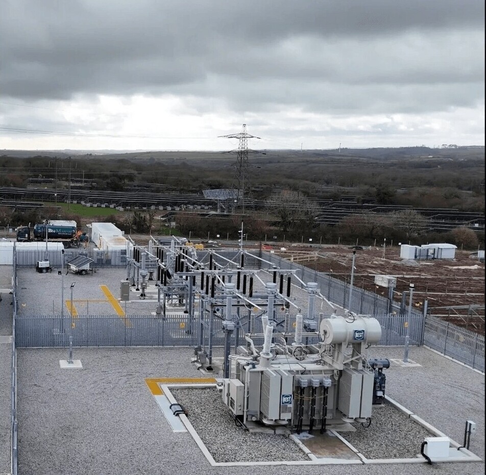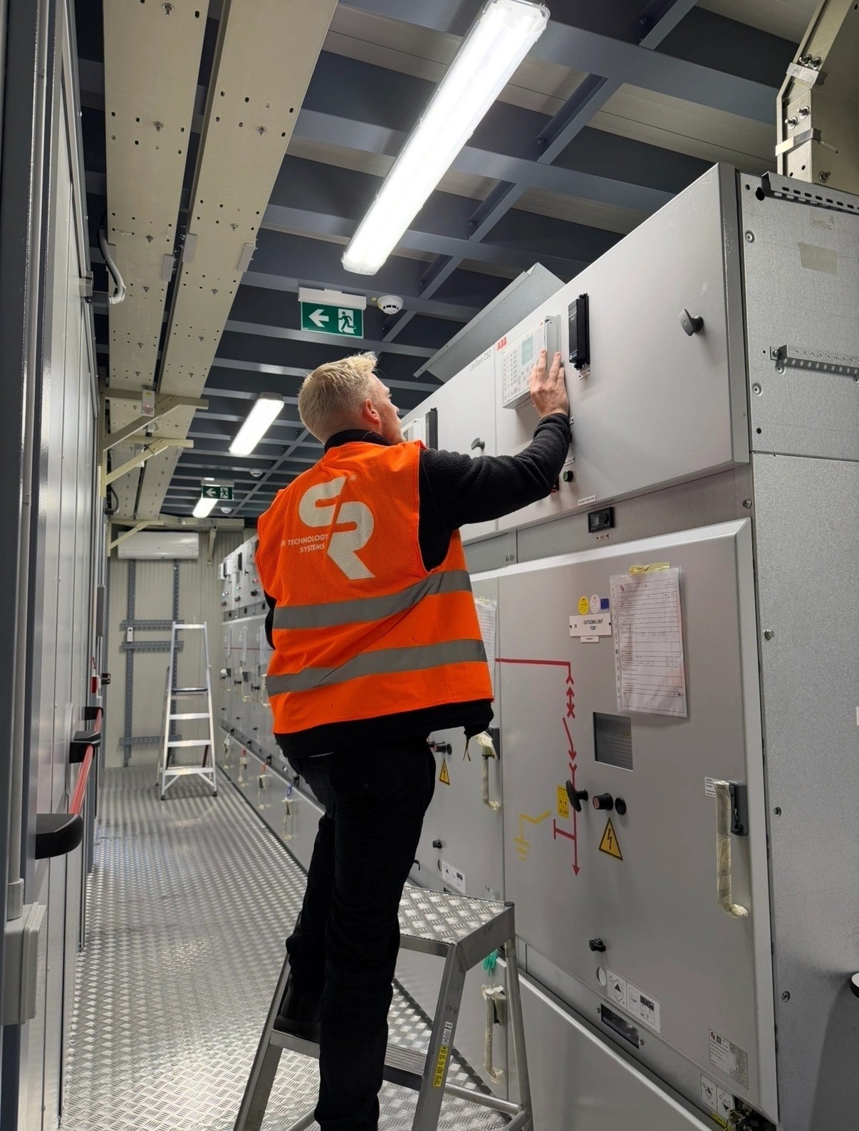
Protection coordination study UK: catching grading errors on site
Grading errors often appear during commissioning because models, relay files and site wiring do not always match. This article explains practical checks before energisation.
Chief Executive Officer, High Voltage Commissioning Ltd
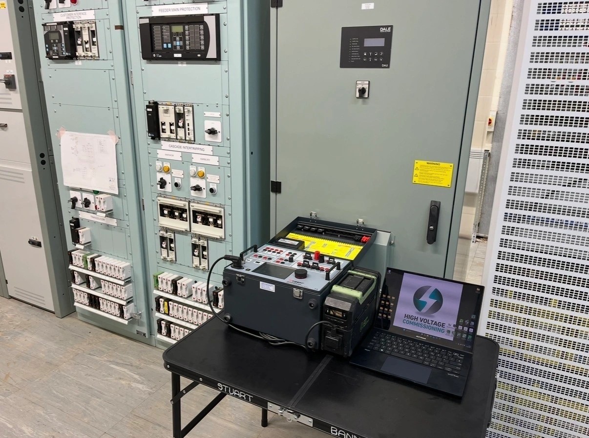
A protection coordination study UK engineers can trust is not just a set of curves in a report. It has to survive contact with the actual switchgear, CTs, relays, transformers, embedded generation settings, DNO requirements and the way the job has been built. I have found more grading issues during commissioning than I would like, not because the study was ignored, but because the assumptions inside it were not proven on site before energisation.
Why are grading errors found on site rather than in the study?
Most grading studies are technically sound within the information given to the engineer. The problem is usually the information chain between design, procurement, panel build, installation and commissioning.
On paper, the model may show a clean sequence: LV ACB clears first, then transformer HV relay, then upstream DNO or private network incomer. On site, I have seen that sequence fail for basic reasons:
- CT ratios changed during procurement but the study still used the tender ratio.
- Relay setting files issued for construction did not match the final approved grading report.
- Earth fault elements were enabled in the relay but not shown on the time-current curve printout.
- Transformer vector group and earthing assumptions were not reflected in residual earth fault protection.
- LV protection settings were altered by the switchboard manufacturer after the HV study had been completed.
- DNO interface settings were received late and not back-checked against the private network settings.
The study is a model. Commissioning proves whether the installed system matches that model. If those two things are treated as separate activities, grading errors move from the office to the substation.
Which assumptions in a grading study cause the most trouble?
CT ratio, class and connection are not minor details
CT information is one of the most common sources of trouble. I have attended sites where the relay setting schedule assumed 400/1 CTs, the panel drawings showed 600/1, and the nameplates fitted in the switchgear were 800/1. Each item made sense at a different point in the project, but only one was actually in service.
That affects more than pickup current. It affects high-set elements, earth fault sensitivity, REF stability, transformer inrush margins and whether secondary injection results make sense. A relay can pass a secondary injection test and still be wrong for the primary plant if the CT ratio used in the calculation is wrong.
I always check:
- CT nameplate against the latest drawings and protection schedule.
- Ratio selected on any multi-ratio CTs.
- Polarity markings and actual wiring through the test block.
- Whether protection, metering and REF cores have been swapped.
- Relay CT ratio settings against the physical CTs, not just the setting sheet.
A protection study cannot see a crossed S1/S2 or a CT shorting link left in the wrong position. Commissioning can.
Transformer data often changes after the study is issued
Transformer impedance, rating, tap position and vector group all matter. On larger private networks I have seen the purchased transformer differ from the transformer used in the early grading model. It may be the same MVA rating but a different impedance, or the tap range may not match the initial design assumption.
That can alter fault levels enough to affect instantaneous elements and grading margins. It can also change LV fault current availability, which then affects whether downstream LV devices operate quickly enough to avoid upstream HV tripping.
Before energisation I want the protection study checked against the transformer nameplate and the final test certificates. If the model says 6% impedance and the transformer on site is 8%, I do not treat that as paperwork. I ask whether the fault level and grading have been recalculated.
How do relay settings go wrong between the report and the panel?
Manual entry and file control create risk
Modern relays are good at storing settings, but they are only as good as the file control around them. I have seen relays commissioned with an old setting file because it was saved on a laptop from a previous issue. I have also seen a single character error in a curve selection turn an intended IEC very inverse element into a different operating characteristic.
The risk increases when several people touch the settings:
- Design engineer issues a setting schedule.
- Protection engineer exports a relay file.
- Panel builder loads a factory test file.
- Commissioning engineer makes site adjustments.
- DNO requests a change to an interface element.
Unless the final relay download is compared back to the approved schedule, there is no guarantee the live relay reflects the study.
Hidden elements are easily missed
Many grading reports show the main phase overcurrent and earth fault curves. The relay, however, may have other active elements:
- Negative sequence overcurrent.
- Sensitive earth fault.
- Standby earth fault.
- Broken conductor.
- Thermal overload.
- Arc flash or zone interlocking inputs.
- Directional elements.
- Autoreclose or blocking logic on DNO interfaces.
I have found high-set elements enabled at default values from factory templates. During a normal secondary injection of the main elements everything looked acceptable, but the relay would have operated instantaneously for faults that should have graded downstream. That is the sort of defect that appears during detailed relay interrogation, not on a curve sheet alone.
What site defects break protection grading before energisation?
Protection grading is not just numbers. Wiring, logic and interlocks can defeat a correct study.
Examples I have found during commissioning include:
- Trip circuit wired to the wrong circuit breaker in a multi-panel board.
- Relay trip output mapped correctly in software but not connected at the terminal rail.
- Intertrip receive contact inverted, giving a healthy indication while the trip path was unavailable.
- CT star point earthed in two locations, causing instability concerns.
- Earth fault residual connection made from the wrong CT core.
- Test block links not matching the drawing, so injection tests did not prove the whole circuit.
- Trip coil supervision wired across the wrong supply polarity.
One site issue that stays in my mind involved two feeders with identical relays and adjacent test blocks. The settings were correct. The study was correct. The problem was that the trip wiring had been transposed during panel modification. A fault on one feeder would have tripped the other breaker. That was caught by point-to-point trip testing, not by looking at grading curves.
Under the Electricity at Work Regulations 1989, we have to prevent danger so far as is reasonably practicable. For HV work, that means proving the protection and tripping arrangements before equipment is made live, under the correct safety rules, permits to work and sanctions for test. A protection report alone is not proof that the installed trip path is safe.
How should engineers catch grading errors before energisation?
Start with a document freeze and discrepancy log
Before commissioning starts, I like to establish what documents are being used as the control set:
- Approved protection coordination and grading study.
- Final relay setting schedule.
- Relay configuration files and logic diagrams.
- Switchgear schematics and termination drawings.
- CT and VT data.
- Transformer nameplate data and test certificates.
- DNO interface settings, including any ENA/G99 requirements where generation is connected.
- LV ACB/MCCB settings where they affect HV grading.
Then I run a discrepancy log. Not an informal list in someone’s notebook, but a controlled record of anything that does not match. Each discrepancy needs an owner and a close-out decision. Some items are harmless; some require the study to be revised.
Compare the relay download with the approved settings
I do not rely on the relay display alone. For numerical relays, the final settings should be downloaded and compared with the approved setting file or schedule. This includes:
- CT and VT ratios.
- Curve type and time multiplier.
- Pickup values.
- High-set and instantaneous elements.
- Directional settings.
- Enabled and disabled protection functions.
- Output contacts and trip matrix.
- Blocking, intertripping and logic equations.
If a setting has changed on site, I want to know who authorised it and whether the grading study still supports it.
What commissioning tests prove the study has been implemented?
A sensible test sequence links the study to the plant. It is not just about making a relay operate.
| Test stage | What it proves |
|---|---|
| Drawing and nameplate check | The study data matches installed equipment |
| Secondary injection | Relay elements operate at the intended pickups and times |
| Trip circuit testing | The correct breaker trips from the correct relay output |
| Primary injection where practicable | CT ratio, polarity and wiring are proven through the circuit |
| Functional intertrip tests | Upstream, downstream and DNO interface logic behaves as intended |
Secondary injection is useful, but it has limits. It proves the relay response to injected current and voltage. It does not automatically prove CT polarity, primary ratio selection or that the correct breaker will open. That is why functional trip testing is critical.
Where primary injection is practicable, it is valuable for proving CT circuits. On some HV panels access and equipment limitations make full primary testing difficult, so the commissioning plan needs to state what is being proven by which method. Assumptions should not be hidden.
How do DNO interfaces and G99 schemes affect grading?
DNO interface protection adds another layer. On embedded generation schemes, ENA/G99 settings for loss of mains, voltage and frequency sit alongside overcurrent and earth fault grading. The G99 relay may not be part of the fault grading curve in the same way as an overcurrent relay, but its trip outputs and interlocks can still affect energisation and operation.
Common issues I see around DNO interfaces include:
- Late changes to DNO required settings.
- Intertrip circuits not fully tested end-to-end.
- Export limitation or generator breaker logic not reflected in the commissioning sequence.
- Directional protection assumptions not checked against actual CT and VT polarity.
- DNO witness requirements not allowed for in the programme.
For private 11 kV networks connected to a DNO, the upstream protection may be outside the asset owner’s control. That makes it more important to confirm the agreed point of connection settings and fault level assumptions before energisation. If the upstream relay is faster than expected, your downstream grading margin may not exist.
What should project managers and asset owners ask for?
Project managers do not need to become protection specialists, but they should ask for evidence that joins the design to the installed plant.
I would ask for:
- A final protection study that reflects as-built equipment.
- A signed relay settings comparison against the approved schedule.
- Completed secondary injection records for each active element.
- Trip test records proving the correct breaker operation.
- CT checks covering ratio, polarity and core allocation.
- A closed discrepancy log before energisation.
- Written confirmation of DNO or G99 interface requirements where applicable.
- Clear records of any setting changes made during commissioning.
If energisation is being planned while protection discrepancies remain open, the risk needs to be understood and formally managed. In my view, unexplained protection differences should stop energisation until resolved. A programme delay is easier to explain than a misgraded fault that trips a whole site or leaves faulty plant connected.
What is the practical lesson from site?
The best grading studies I have worked with were not necessarily the thickest reports. They were the ones where the assumptions were clear, the settings were controlled, and the commissioning team had enough information to prove the installation against the model.
Grading errors are usually found on site because the real installation has moved away from the study in small steps. A CT ratio changes, a relay file is revised, an LV setting is adjusted, a DNO setting arrives late, a wiring modification is made during panel build. Each change may look manageable. Together, they can remove the grading margin the network relies on.
My approach is simple: treat the protection coordination study as a live reference until energisation, not as a design deliverable that is filed away. Check the plant against it. Check the relay against it. Check the trip circuit against it. Then record what has actually been proven.
That is how grading errors are caught before the first fault proves them for you.
— Stuart Banner
Need this done on your network?
HV commissioning, SAP provision, protection studies and maintenance across the UK.