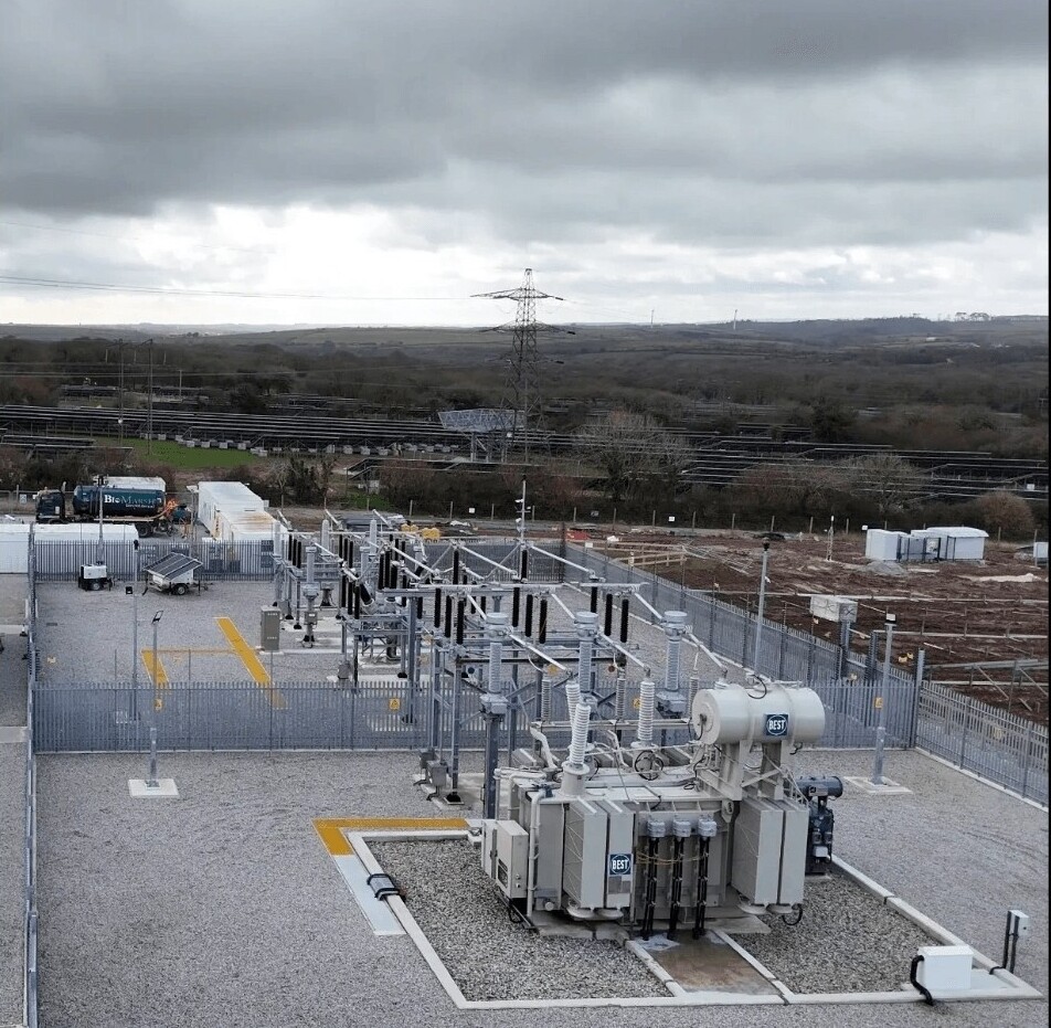
Five protection settings mistakes we keep finding on UK HV networks
Most protection problems we find during commissioning are not relay faults. They are settings and scheme errors that survived design review and only appear under injection testing. These are the five we encounter most often, and how to find them before energisation.
Chief Executive Officer, High Voltage Commissioning Ltd
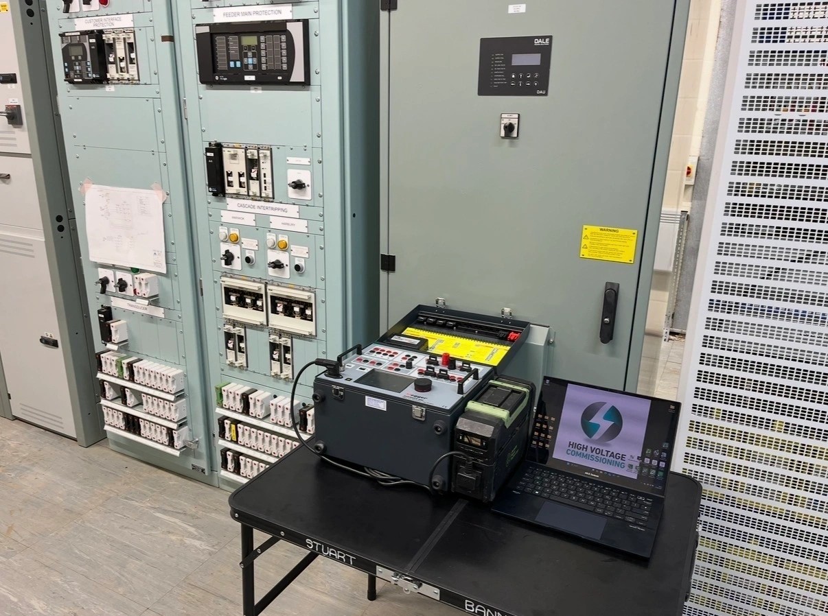
Modern numerical relays are extremely reliable. In fifteen years of testing them I can count the genuine hardware failures on one hand. What fails, repeatedly, is the space between the grading study and the configuration file.
Here are the five errors we find most often.
1. CT ratio mismatch between the study, the setting file and the nameplate
The grading study assumes 400/1. The relay is configured for 400/1. The installed CT is 300/1 because that was what arrived on site. Every current-based setting is now wrong by a third. Primary injection catches this immediately; a paper review of the setting file never will.
2. Grading against a superseded fault level
Fault levels change. DNO reinforcement, new generation, a network reconfiguration — and the study in your document register is two years old. We ask for the fault level letter and its date on every job. If the study predates it, the grading needs revisiting before we energise, not after.
3. Directional elements with the wrong polarising reference
Directional overcurrent and earth fault elements depend entirely on the polarising quantity and the assumed forward direction. Get the VT connection, the CT polarity or the characteristic angle wrong and the element operates confidently in the wrong direction. This is only ever proved by injection with correct phase angles, and by on-load directional checks after energisation.
4. Trip paths that were never proved end to end
The relay picks up. The relay times correctly. The relay closes its trip contact. And the contact is wired to a spare terminal, or the intertrip to the adjacent substation was assumed rather than proved. Every trip path needs to be proved to the breaker it is supposed to open, including remote and interlocking trips, and including the ones nobody wants to test because they involve two sites and a radio.
5. Blocking and interlocking logic assumed rather than tested
Blocked overcurrent schemes, busbar blocking, autoreclose blocking, breaker fail logic. These schemes work correctly in the logic diagram and fail in the configuration. Testing them requires deliberately building the fault scenarios the scheme was designed for — including the ones where the scheme is supposed to not operate.
How to find these before energisation
- Freeze the setting schedule before commissioning starts and treat changes as controlled revisions
- Verify installed CT and VT ratios physically against the schedule
- Do primary injection on new CT circuits — not just secondary
- Write a test plan per protection function, including expected non-operation cases
- Prove every trip path to the breaker, and every intertrip across both sites
- Repeat directional and differential stability checks on load after energisation
None of this is exotic. It is systematic testing against a frozen design, done by someone whose job is to disprove the scheme rather than confirm it.
— Stuart Banner
Need this done on your network?
HV commissioning, SAP provision, protection studies and maintenance across the UK.